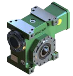
The following headings include info on essential aspects for selection and proper utilization of gearbox.
For unique data around the gearbox variety,see the relevant chapters.
one.0 OUTPUT TORQUE
one.one Rated output torque
Mn2 [Nm]
The torque that will be transmitted continuously through the output shaft, with all the gear unit operated under a service element fs = one.
1.2 Required torque
Mr2 [Nm]
The torque demand based mostly on application requirement. It can be encouraged to become equal to or significantly less than torque Mn2 the gearbox under review is rated for.
1.three Calculated torque
Mc2 [Nm]
Computational torque value to become used when picking the gearbox.
It really is calculated looking at the needed torque Mr2 and support issue fs, as per the connection right here after:Mc2 = Mr2 ?¡è fs ?¨¹ Mn2
2.0 Electrical power
two.one Rated input power
Pn1 [kW]
The parameter can be located from the gearbox rating charts and represents the KW that may be securely transmitted to your gearbox, based mostly on input velocity n1 and services element fs= one.
two.two Rated output power
Pn2 [kW]
This value may be the electrical power transmitted at gearbox output. it could be calculated with the following formulas:
Pn2 = Pn1 ?¡è |?d
Pn2= Mn2*n2/9550
3.0 EFFICIENCY
Efficiency can be a parameter which features a main influence over the sizing of particular applications, and basically will depend on gear 
Bear in mind that these values are only accomplished following the unit is run in and is on the working temperature.
3.one Dynamic efficiency
[|?d]
The dynamic efficiency could be the relationship of energy delivered at output shaft P2 to electrical power utilized at input shaft P1:
|?d =P2/P1
3.2 Static efficiency[|?s]
Efficiency obtained at start-up of your gearbox. Though that is typically not major element for helical gears, it could be alternatively important when picking out worm gearmotors working under intermittent duty.
4.0 Support Component
The support factor (fs ) is dependent upon the operating disorders the gearbox is subjected to the parameters that must be taken into consideration to pick the most sufficient servies factor effectively comprise:
one. type of load on the operated machine : A – B – C
two. length of each day operating time: hours/day(?¡Â)
three. start-up frequency: starts/hour (*)
Form of LOAD: A – uniform,fa?¨¹0.three
B – moderate shocks, fa?¨¹3
C – heavy shocks, fa?¨¹10
fa=Je/Jm
–Je(kgm2) minute on the external inertia lowered in the drive shaft
–Jm(kgm2) minute of inertia of motor
–If fa>10 please make contact with our Technical Service
A -Screw feeders for light materials, supporters, assembly lines, conveyor belts for light resources, compact mixers, lifts, cleansing machines, fillers, handle machines.
B -Winding products, woodworking machine feeders, goods lifts, balancers,threading machines, medium mixers, conveyor belts for hefty resources,winches, sliding doors, fertilizer scrapers, packing machines, concrete mixers, crane mechanisms, milling cutters, folding machines, gear pumps.
C -Mixers for heavy components, shears, presses, centrifuges, rotating supports, winches and lifts for hefty materials, grinding lathes, stone mills, bucket elevators, drilling machines, hammer mills, cam presses, folding machines, turntables, tumbling barrels, vibrators, shredders.
