QD Sprocket
The QD sprocket is a type of chain sprocket that features a unique quick-detachable (QD) design. It consists of a hub, teeth or cogs, and a QD bushing. The hub is the central part of the sprocket that connects to the driving shaft. The teeth or cogs engage with the chain, enabling the transfer of rotational motion. The QD bushing allows for easy installation and removal of the sprocket.
QD Sprocket Catalog
Showing 1–12 of 26 results
-
QD Sprocket No.35 Single Type
-
QD Sprocket No.35-2 Double Type
-
QD Sprocket No.35-3 Triple Type
-
QD Sprocket No.41 Single Type
-
QD Sprocket No.40 Single Type
-
QD Sprocket No.40-2 Double Type
-
QD Sprocket No.40-3 Triple Type
-
QD Sprocket No.50 Single Type
-
QD Sprocket No.50-2 Double Type
-
QD Sprocket No.50-3 Triple Type
-
QD Sprocket No.60 Single Type
-
QD Sprocket No.60-2 Double Type
Types of QD Sprocket

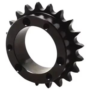
Single QD Sprocket

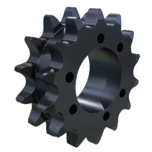
Double QD Sprocket

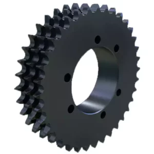
Triple QD Sprocket

Manufacturing Process of QD Sprockets
The manufacturing of QD sprockets follows a series of precise steps to ensure they meet high-quality standards for performance and durability. Here’s a breakdown of the process:
Raw Material Preparation: The manufacturing begins with high-quality steel or other materials selected for their strength and durability. These materials must be free of impurities and prepared to meet the specifications required for the final product.
Cutting or Forging: The raw material is then cut or forged into the basic shape of the sprocket. This step ensures that the material is molded into the correct size and dimensions to meet the design specifications of the sprocket.
Machining: In this phase, the sprocket undergoes CNC machining, which involves precision operations such as drilling, turning, and milling. These steps refine the sprocket’s shape and ensure that all features, including holes for the key and bolts, are accurately created.
Tooth Rolling: Once the basic shape is formed, the next step is rolling the teeth onto the sprocket. This process is critical because it determines the durability of the sprocket in motion. The teeth must be cut or rolled to the correct pitch and depth to ensure proper engagement with the chain.
Heat Treatment: After the teeth are formed, heat treatment is applied to improve the material’s hardness and strength. This process is vital to ensure that the sprocket can withstand the forces it will experience during operation without wearing prematurely or failing.
Surface Treatment: The sprocket is then subjected to surface treatments such as plating, painting, or coating to improve corrosion resistance and extend its service life. This step is crucial for sprockets used in harsh environments where exposure to moisture and chemicals may cause premature wear.
Quality Inspection: After all manufacturing steps, each QD sprocket undergoes a rigorous quality control process to ensure that it meets industry standards. This includes dimensional inspections, surface testing, and stress tests to verify the sprocket’s performance under load.
Tebsa specializes in the production and sale of high-quality QD sprockets, providing precision-engineered solutions for various industrial applications. As the Argentine branch of Hangzhou Ever-Power Transmission Co., Ltd., Tebsa leverages advanced manufacturing techniques and a focus on quality control to deliver reliable and durable sprockets that meet global industry standards. Our QD sprockets are designed for easy installation and superior performance, offering customers both cost-effective and high-performance solutions.
With a team dedicated to customer satisfaction, Tebsa offers not only exceptional products but also personalized support to ensure each sprocket meets the unique needs of our clients. Whether it’s for machinery, conveyor systems, or other heavy-duty applications, Tebsa provides the expertise and custom solutions that industries demand. We are committed to maintaining efficient production timelines and fast delivery, allowing our clients to meet their operational needs without delay.

If you are seeking high-quality, custom QD sprockets, Tebsa is the right choice. Our products stand out for their durability, precise engineering, and cost-effectiveness. Reach out to us today to learn more about our sprockets and how we can assist in optimizing your equipment’s performance.
What is QD Sprocket
A QD Sprocket, where “QD” stands for “Quick Detachable,” is a specially designed sprocket that simplifies installation and maintenance. It features a QD bushing, a tapered sleeve that securely attaches the sprocket to the shaft. The QD bushing can be easily installed and removed, making sprocket replacement and maintenance much more efficient.
The main components of a QD sprocket include:
- Sprocket body: A round metal component with teeth that engage with the chain.
- QD bushing: A tapered sleeve with an internal keyway and external threads, used to mount the sprocket onto the shaft.
- Fasteners: A set of bolts and nuts that secure the QD bushing to the sprocket and clamp it firmly onto the shaft by tightening the bolts.

Easy Installation and Removal
- The design of the QD bushing allows the sprocket to be quickly installed and removed without complicated tools or equipment.
- Installation or removal can be completed by simply tightening or loosening the bolts, greatly reducing downtime and maintenance costs.
Strong adaptability:
- QD sprockets are suitable for a variety of shaft diameters. By choosing different specifications of QD bushings, they can be easily adapted to shafts of different sizes.
- It can be used in a variety of different applications, such as industrial machinery, agricultural machinery, construction machinery, etc.
High load capacity
- QD sprockets are usually made of high-strength materials such as carbon steel, alloy steel or stainless steel, and can withstand high loads and torques.
- They are suitable for low to medium load applications, but can also be used for heavy load applications in some cases.
Durability
- The design of the QD bushing allows the sprocket to be quickly installed and removed without complicated tools or equipment.
- Installation or removal can be completed by simply tightening or loosening the bolts, greatly reducing downtime and maintenance costs.
Cost-effectiveness
- While the initial cost may be slightly higher than other types of sprockets, its quick installation and removal characteristics reduce long-term maintenance costs.
- Reduces downtime due to sprocket replacement and improves overall production efficiency.
Standardization
- QD sprockets follow international standards such as ANSI, DIN, etc., ensuring interchangeability and compatibility.
- The standardized design makes it easier for users to find suitable replacement parts.

Install QD Type Bushings
1. Clean the shaft, bushing bore, outside of bushing and the sprocket/sheave hub bore of all oil, paint and dirt. File away any burrs.
Note: Do not lubricate the bushing taper, hub taper, bushing bore or the shaft. Doing so may result in sprocket/sheave hub fracture. DO NOT USE LUBRICANTS.
2. For a conventional mount, assemble the sprocket/sheave and bushing combination by sliding the sprocket/sheave taper bore into position over the mating tapered bushing surface. Align the unthreaded holes in the sprocket/sheave hub with the threaded holes in the flange of the bushing.
Hand-tighten the cap screws with lock washers installed. The sprocket/sheave and bushing assembly will mount onto the shaft, with the bushing flange facing inward.
Some sprocket/sheave assemblies will allow a reverse mount procedure. This results in the bushing flange facing outward, but still allows the cap screw installation from the outside of the assembly. The cap screws fit through the unthreaded holes of the bushing flange and into the
threaded holes of the sprocket/sheave hub.
3. With the key resting in the shaft keyway, position the assembly onto the shaft allowing for small axial movement of the sprocket/sheave, which will occur during the tightening process.
When installing large or heavy parts in a conventional mount, it may be easier to mount the key and bushing on the shaft first, then place the sprocket/sheave on the bushing and align the holes.
Note: When mounting sprockets/sheaves on a vertical shaft, pre-cautions must be taken to prevent the sprocket/sheave and/or bushing from falling during installation.
4. Alternately tighten the cap screws until the sprocket/sheave and bushing tapers are completely seated together (use approx. half of the recommended bolt torque; see Table ).
5. Check the alignment and axial sprocket/sheave run out (wobble), and correct as necessary.
6. Continue alternate tightening of the cap screws to the recommended torque values specified in Table below. Do not tighten cap screws further once the recommended torque is reached.
Note: Excessive bolt torque can cause sprocket/sheave and/or bushing breakage. When properly mounted, a gap between the bushing flange and sprocket/sheave should exist.
7. Tighten the set screw, when available, to hold the key securely during operation.
| Bushing style | Bolt(in) | Torque Wrench | ||
| Qty | Size | lb-ft | lb-in | |
| H | 2 | 1/4 x 3/4 | 7.9 | 95 |
| JA | 3 | 10-24 x 1 | 4.5 | 54 |
| SH&SDS | 3 | 1/4-20 x 1 3/8 | 9.0 | 108 |
| SD | 3 | 1/4-20 x 1 7/8 | 9.0 | 108 |
| SK | 3 | 5/16-18 x 2 | 15.0 | 180 |
| SF | 3 | 3/8-16 x 2 | 30.0 | 360 |
| E | 3 | 1/2-13 x 2 3/4 | 60.0 | 720 |
| F | 3 | 9/16-12 x 3 5/8 | 75.0 | 900 |
| J | 3 | 5/8-11 x 4 1/2 | 135.0 | 1620 |
| M | 4 | 3/4-10 x 6 3/4 | 225.0 | 2700 |
| N | 4 | 7/8-9 x 8 | 300.0 | 3600 |
| P | 4 | 1-8 x 9 1/2 | 450.0 | 5400 |
| W | 4 | 1 1/8-7 x 11 1/2 | 600.0 | 7200 |
| S | 5 | 1 1/4-7 x 15 1/2 | 750.0 | 9000 |

Single QD Sprocket
To remove a QD sprocket, follow these steps:
Start by loosening and removing all the mounting bolts. Then, insert cap screws into each of the threaded jack screw holes. Begin loosening the bushing by tightening the screw furthest from the bushing saw slot first. After that, alternately tighten the remaining screws. It’s important to tighten the screws in small, equal increments, gradually applying pressure until the tapered sprocket or sheave and the bushing disengage.
Note: Applying excessive or uneven pressure on the bolts can damage the bushing flange, making it impossible to remove the sprocket or sheave without causing destruction.